I started this post to showcase my first electrical circuit, a motion detecting rope light, but it begins with a rant about the clutter I’ve accumulated over my short time as hobbyist electrical engineer. After the short rant, I basically present a walkthrough of the project along with the wiring schematic, the code, and a video showing the light in action.
For about a year now I have been hobbying out in electrical engineering. I’ve spent a lot of my spare time browsing through the interwebs, bookmarking resources, purchasing all of the components I would need, and otherwise preparing myself to build cool stuff. So, after several months of purchasing all the parts an aspiring hardware hacker might need, my office morphed from a neat, well-organized space into a disaster area full of sensors, switches, wires, and the like. I now have a host of plastic containers to keep the mass of stuff at bay, but looking around my desk now I could probably use some more. This hobby brings about a lot of clutter.
Alright, to the cool part! I’ve got this inside stairwell that does a great job bridging the gap between the upstairs and downstairs floors, but it’s crazy dark and a little precarious to walk down. It has a light, but it’s a single-pole switch at the bottom, meaning the only time I can put it to use is if my journey begins and ends at the bottom of the staircase. I was sitting around one day thinking about how much of an inconvenience it is to use my phone’s flashlight to walk when it hit me: a rope light with a motion detector.
I already had most of the fundamentals by this time: a breadboard, a bunch of power supplies, resistors, transistors, and the like; all I really needed to buy was the rope light itself and a motion detector. I purchased a few motion detectors on eBay and a rope light that plugs into a 120v wall outlet from a local hardware store. Ideally, I would have used a DC powered 12v rope light, but I’m a little impatient sometimes and the fastest shipping time I could find on one like that was 3+ weeks from Hong Kong. Finally, I bought a solid state relay so that I could switch the AC with my little DC circuit. The relay I bought can only handle 4 amps of current, so it couldn’t safely switch electricity directly from the outlet (where it may potentially see 10 or more amps), but the rope light had a fused plug that would only allow 0.3 amps to flow, meaning my relay’s 4 amp limit was more than sufficient.
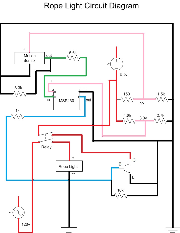
As you can see in the diagram, I have two power sources. It’s kind of inconvenient, but I figured I would just put them on an extension cord since I don’t have an outlet by the stairs and as such need the length anyway. The circuit basically works like this: I cut the hot wire on the rope light and hooked it to the two AC posts on the relay. This means there is always 120v sitting at the first post on the relay waiting to be grounded to the second post. When I flow current through the DC pins on the relay, the AC side closes, illuminating the rope light magnificently. The DC side of the relay is similar to the AC side in that voltage is always present (but this time on both pins), and I use a NPN transistor to ground the voltage and close the ciruit (which in turn closes the AC circuit letting voltage flow from the first post to the second post and through the light). When the motion detector senses motion, it sends voltage out to the MSP430 which is programmed to send voltage to the base lead B on the transistor, which then allows current to flow from the collector lead C to the emitter lead E.
The job of the MSP430 is really just to send voltage to the base of the transistor and hold that voltage for a set amount of time. When the transistor gets voltage on the base pin it grounds any voltage on the collector pin through the emitter pin. Since the DC side of the relay is in line with the collector pin, it is effectively grounded when the MCU sends voltage to the base, which in turn grounds the AC side.
One more thing: the MSP430 takes 3.3v and the motion detector takes 5. Furthermore, I had a 5.5v power supply. That’s why they have separate power sources. I just took some resistors and made some voltage dividers. There are plenty of calculators around the net to help calculate the resistors needed.
Ok, so now it’s time for the code. It starts by including the header file and defining some constants so we can specify which pins to use in a nice readable form. Then comes the function definition for configuring the clock and a volatile unsigned integer declared as such because we don’t want the compiler to try and optimize it and because it will never be negative. The fist line in main is basically standard in MSP430 applications; it stops the watchdog timer from resetting the chip. The second line configures the system clock to operate at 1MHz, reducing the CPU speed to a power-sipping 1 million cycles per second. Knowing this speed is important to the built-in __delay_cycles() function; and the faster our clock speed is, the more cycles we would have to delay to achieve the same amount of time delayed. Next, we tell the MCU which pins we are going to send voltage out of. It is just a series of bits, with a value of 0 meaning that pin is for input and a value of 1 meaning that pin is for output. We are just setting bits saying that the direction of RELAY_OUT and RED_LED are 1. P1IE stands for port 1 interrupt enable and it also takes a series of bits specifying which pins to allow interrupts on. Interrupts use a flag bit to acknowledge when the interrupt has been triggered. We ensure this flag is cleared before we go into low power mode and every time the interrupt routine is called (I’m pretty sure clearing the bit in the interrupt function is unnecessary and should happen automatically when the MCU returns to the low power mode, but I opted for better safe than sorry). We will use this interrupt to wake the MCU from the low power mode that we put it in. There are 4 low power modes, with mode 4 consuming the least power of them all. The code in the interrupt routine is pretty simple and commented well enough. We basically just use that function to send voltage to the relay-grounding transistor and delay for ten million cycles before we stop sending voltage and return to our low power mode.
#include  <msp430.h>

#define RED_LED BIT0
#define MOTION_IN BIT7
#define RELAY_OUT BIT4

void configureClock();
volatile unsigned int i;

void main(void) {
    /* Hold the watchdog timer so it doesn't reset our chip */
    WDTCTL = WDTPW + WDTHOLD;

    /* Configure clock speed */
    configureClock();

    /* Configure pins 4 and 0 on port 1 as output pins */
    P1DIR = RELAY_OUT | RED_LED;

    /* Port 1 interrupts enable for our MOTION_IN pin */
    P1IE |= MOTION_IN;

    /* Clear the MOTION_IN bit in the Port 1 interrupt flag. */
    P1IFG &= ~MOTION_IN;

    /* Go into low power mode 4 with general interrupts enabled */
    __bis_SR_register( LPM4_bits + GIE );
} //end main()


/* Clock configuration */
void configureClock()
{
    // Set system DCO to 1MHz
    BCSCTL1 = CALBC1_1MHZ;
    DCOCTL = CALDCO_1MHZ;
} //end configureClock()


/* Port 1 interrupt service routine function definition followed by the function itself */
void Port_1(void) __attribute__((interrupt(PORT1_VECTOR)));
void Port_1(void) {
    /* Clear the interrupt flag */
    P1IFG &= ~MOTION_IN;

    /* Send current to RELAY_OUT and RED_LED */
    P1OUT = (RELAY_OUT | RED_LED);

    /* Delay roughly 10 seconds by burning cycles
     1MHz clock == 1,000,000 cycles/second * 10 seconds == 10,000,000 cycles to burn
     Since we can't delay 10 million cycles, delay 100,000 cycles 100 times. */
    for(i = 0; i < 100; i++){
      __delay_cycles(100000);
    }

    /* Stop sending current to RELAY_OUT and RED_LED */
    P1OUT &= ~(RELAY_OUT | RED_LED);
} //end Port_1()
And that’s it! Well, not completely it. I also shot a video demonstrating the light in action: